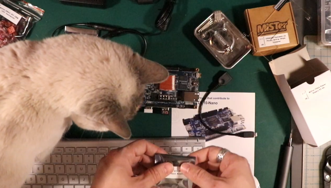
- -> MiSTer FPGA Initial Setup and Network Mounting
Last Updated on May 29, 2023.
What is MiSTer FPGA?
I like to think of MiSTer FPGA as hardware emulation vs the software emulation I’m used to. The MiSTer suite of cores and utilities are designed to be installed on the Terasic DE10-Nano FPGA board, and various add on boards to support more USB components or video/audio output. MiSTer FPGA is a project that coordinates different ‘cores’ (e.g. old computer systems or game consoles) and applies them to the FPGA board, effectively instructing the FPGA board to act as the chipsets of these old retro computer and console systems.
FPGA itself stands for ‘Field Programmable Gate Array’. It is a type of integrated circuit that can be programmed by the user to perform specific functions. So think of it like a blank slate chip that you can program to act as another chip. That’s how we do the hardware emulation. Since this reprogramming of the chip can happen without having to manufacture a new chip, we can use the term ‘Field Programmable’ – you can reprogram it in the field, outside of a chip manufacturing plant.
Why MiSTer FPGA?
I wanted to try MiSTer FPGA because I’ve never messed with hardware emulation. It’s always been on the real deal or with software emulation (like DOSBOX or VICE). My understanding is that lag is nearly non-existent when compared to emulators, and the ‘cores’ (the systems we’re emulating) run more true to the original hardware than their software emulating counterparts. Want to know some of the cores directly supported? Check out the core list here.
My motivation for doing this is because while I like to have genuine retro systems of the old systems I had as a child, I don’t care to try to own an Apple IIe, or an Atari ST. I was a Commodore guy, so while I want to tinker with those systems, I definitely don’t want to hit up e-bay and start trying to build my own piece-by-piece setup for a system I never owned or had no vested interest in. (See how I through that line in there? I never owned a Commodore PET, but I wouldn’t turn a free one down)
The MiSTer Wiki page has excellent information, tutorials, and references.
The Parts List
So from the hardware standpoint, we need at a minimum the Terasic DE10-Nano board. This is the specific model of FPGA board that the open source MiSTer FPGA project software (Mr. Fusion) expects to be installed on, so it’s a must. After that you have all sorts of add ons and adapters (adapters to even hook up old console specific adapters like light guns) to enhance your retro gaming experience. I went with the following (links to where you could find them included – not necessarily the only place, but at least one place)
- Terasic DE10-Nano board – The bare minimum as stated above. I ordered mine from Terasic directly.
- USB Hub V2.1 for MiSTer – This gives us more USB ports to connect keyboards, mice, joysticks, etc. to the Terasic board. It’s a powered HUB that is designed to mount underneath the Terasic. It comes with a splitter power cable to split your power supply between the USB board and the Terasic (but if you use the digital IO board you don’t use the splitter, see that part for more detail)
- 128MB SDRam Module – Not required for all the cores, but it is required for enough of them that I wanted to mess with. This slides into the top part of the Terasic board. You can see the cores that require SDRam here.
- I/O Boards: There are typically two I/O boards that people use for this. I’m going to try both, but you only install one at a time. Generally, for those that want to stream HDMI but play on a CRT, you’ll get the Analog board. The Digital board offers some extra expansion capabilities, though. Regardless of which one you get, this board sits on TOP of the Terasic, so when combined with the USB hub below, the Terasic is in the middle. Of note are the three switch buttons on top to easily access Reset, OSD (On screen display), and user defined functions. Cases for these are also available, and assume you have the standard 3 board setup (USB board + Terasic board + IO Board)
- MiSTer Digital IO Board v1.2 – The MiSTer FPGA Digital IO Board v1.2 provides the following features: a dedicated power switch to turn the unit on and off with over-voltage protection, a 3.5mm audio jack for ADC In (Tape Input) a separate ADC-In addon board is not required, 3.5mm Mini-TOSLINK & Digital TOSLINK Connectors, a secondary microSD card slot the functionality depends upon the core being used, a fan speed control jumper providing 3.3 volts or 5 volts, three status LEDs (red, yellow, green), three large push buttons providing system reset, on screen display menu and game reset, an expansion connector in the form of a USB 3.0 connector however this is not for standard USB devices. If you use this board, it comes with a cable so you power your entire setup through this board, power goes through the GPIO pins into the Terasic, and then you use the included barrel cable to go from the Terasic to the USB board. So one power cable powers all three boards connected together. Acrylic Case Link
- MiSTer Analog IO Board v6.1 – The MiSTer FPGA Analog IO board v6.1 includes the following useful features: a VGA (DB15) connector allowing for the output of a VGA/RGB/YPbPr signal depending on the cable being used, a 3.5mm audio jack with Mini-TOSLINK providing analog audio output and digital audio output, a secondary microSD card slot the functionality depends upon the core being used, a fan speed control providing a 3.3 volt / 5 volt selector jumper, a status LED control jumper allowing switching on or off the built in LEDs, a Sync-on-Green switch, three status LEDs (red, yellow, green), three large push buttons providing system reset, on screen display menu and game reset, an expansion connector in the form of a USB 3.0 connector however this is not for standard USB devices. Acrylic Case Link
- Configuration of the video output signal on the IO board is controlled via the MiSTer.ini file, more information on how to configure and download of the MiSTer.ini file see the https://github.com/MiSTer-devel/Wiki_MiSTer/wiki/Configuration-Files configuration
- Wifi/Bluetooth USB Dongles – Generally, I think you can use whatever ones you may already have. Terasic sells some from their site, I used some I already had. They fit nicely into the USB board to give you connectivity as you desire. Not every dongle dangles properly, so here are some recommended adapters for Wifi and Bluetooth.
I also picked up some more ‘odd’ add ons for this as well, more specific to my gaming taste:
- MiSTer SNAC-IEC CBM 1541 Connector – I believe with this I can hook up a real 1541 drive to the kit and use it with the C64 core.
- Ultimate Dameon x2 Player MiSTer FPGA adapter – The Ultimate Deamon PRO USB Dual Encoder for ATARI / SEGA MEGADRIVE / GENESIS. This small form-factor USB adapter makes it possible to use SEGA MEGADRIVE / GENESIS controllers on your PC (Windows, Mac OS X, Linux), Raspberry Pi or MiSTer. The adapter has a native 1ms/1000Hz polling rate so input lag is minimal (the average is 0.75ms with a wired controller). Fully assembled in a Aluminium enclosure and includes USB-C cable to connect this adapter to your favorite setup. (from ultimatemister.com)
- MiSTer RTC Real Time Clock Board 1.4 – For cores that use a clock, mainly if your FPGA kit isn’t going to be internet connected for automatic time syncing, this one’s for you. I don’t believe you need this if you’ll have internet connectivity, though.
Putting the parts together
While you don’t *need* a digital IO board or USB hub connected to your DE10-Nano, it sure makes things easier. Our final configuration when this is setup will be the DE10-Nano sandwiched in between the USB hub board on the bottom, and the digital IO board on the top. Wrap the acrylic case around it and we’re done.
A note on orientation.
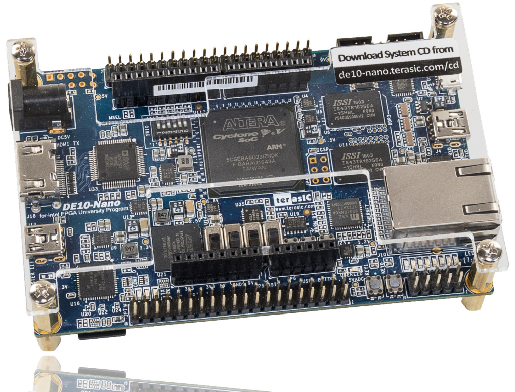
When I say ‘top’ or ‘right’, I’m orienting my Nano like the pictures on Terasic’s website. The ethernet adapter is on the right side when the board is facing up:
Heatsink
Nothing wrong with that. Picked mine up from https://misterfpga.co.uk/product/mister-fpga-ultimate-heatsink/, made to fit the Cyclone V SoC on the DE10-Nano board.
USB HUB Board
The USB Hub board sits below the DE10-Nano, and you’ll need to remove the standoffs from the Nano (I gently twisted with pliers, keep the screws for later but you’ll need to remove them) so that you can mount the USB board below it. On the ethernet side of the Nano, on the very top right, there’s the USB-Micro style OTG (On The Go) port, which is how we connect the HUB to the Nano. My board comes with a slick adapter that plugs into four pins of the USB board:


and then zig zags up and out to the plug into the Nano’s OTG port:

So with the standoffs screwed into each other (leaving the top screws since we’ll be putting the digital board on top), we’re ready to continue.
128MB SDRam Addon Board
I next installed the ram board. I could have done this prior to the USB board, but if nothing else I wanted to do it before a placed the I/O board on top of the Nano. The two large SDRam chips face the inside of the nano for my version, and there’s a label on the opposite side that says ‘this side faces outwards’, so that helps orient you. The SDRam goes into the pin header on the TOP of the Nano.

Digital IO Board (Or Analog if you have that)
Next up is the IO Board, but before we install it, (for Digital IO Boards only), we need to flip a switch on the Nano. Namely, SW3, and it’s right here (in our orientation, SW3 is on the left side of the bank, SW0 is on the right side)

After flipping it on (UP) (and ONLY for the digital IO board – for the analog IO board, all switches should be down/off), we’re ready to put the Digital board on top. Our orientation has the ‘green’ LED above the Red LED, this is how the IO board will look when putting it on top of the Nano if you’re using the orientation we are for our Nano (ethernet port on the right side). We also put another set of standoffs on top of the Nano for this to rest on.
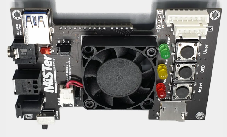
One troublesome thing I noticed was there are more headers (holes) on the Nano then there are pins on the IO board, so you’ll want to be careful. With our orientation we’ve been using, the digital IO board carefully slides into the pins on the Nano. Gently make sure all of the pins line up. On the both top and bottom sides of the Nano, you’ll have more headers (holes) on the Nano then you actually will pins from the digital IO board. Here are some shots from the misterfpga.co.uk site that show the differences of top and bottom headers/vs pins:


At pretty much anytime during this install, we could have turned the whole thing on and tried things out (hooking up a keyboard, HDMI, and power), but we’re going to cover that later. For now, on to the Acrylic Case. (If you’re not using a case, you can screw the IO board into the brass standoffs it should be touching – but if you ARE using a case, no screws yet)
Acrylic Case
More parts! Don’t worry – it’s not uncommon that you will leave here with more brass standoffs than you started with, as individual parts often come with extras. My case is designed for the digital IO board AND USB board in the mix. There are other case variants that use the Analog IO board and USB board, naturally.
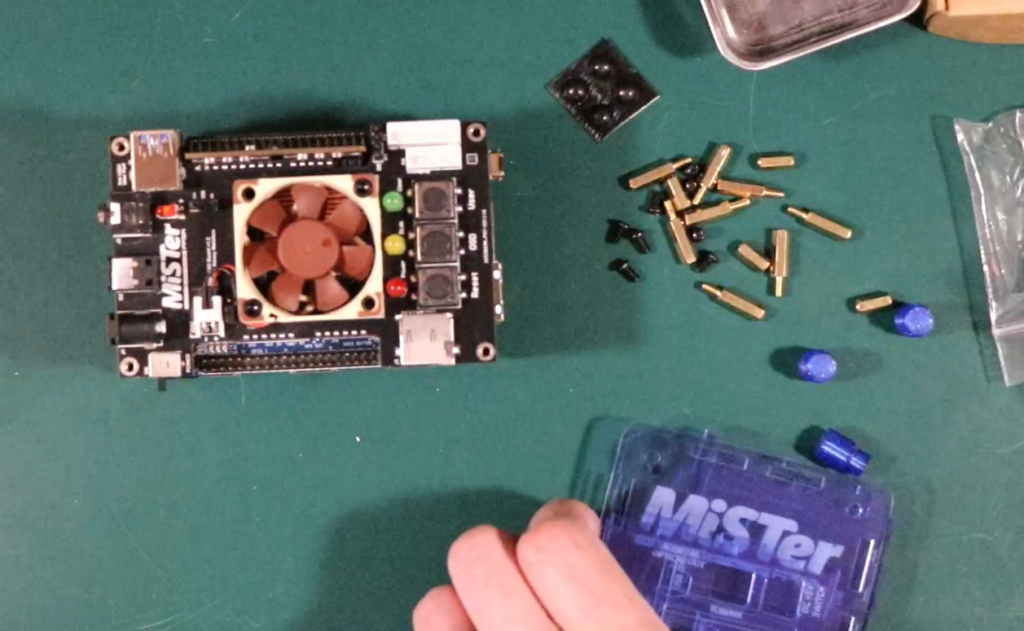
Put the top standoffs into your digital IO board now, before you start building your case walls. (You can do it afterwards, it’s just annoying). Rest the MiSTer on top of the bottom part of the case, and build your walls up by aligning holes to case sides. The tabs on the case sides slid together easily enough for me.

The part that was roughest for me was the three little separate plastic buttons that rest on top of the Digital IO board’s buttons. I found it easiest to put the buttons in the top side of the case, turn the MiSTer upside down, and align the case top and buttons that way.
With the case top on, and making sure the buttons were in place, I put the four screws in to the top of the case, securing the boards and case all together. We’re done assembling our FPGA sandwich!
Power setup
When using this style of kit, where we have the IO board on top of the Nano on top of the USB hub, we really only need to give power to one component, and then we daisy chain power down to the other two boards. We power the Digital IO board directly, which then gives power to the Nano, then we use the included Male to Male barrel connector to go from Nano to USB board. So my power side/HDMI side looks like this:
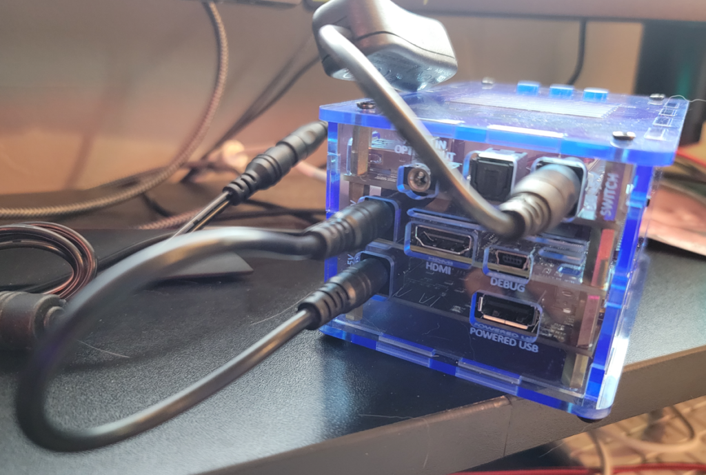
Don’t forget, the Digital IO board also comes with a power switch on the bottom left (a simple slider switch). I’m also using an inline switch power adapter, just make sure you’re turning all the right parts on. I just leave the digital board switch on and use the inline adapter switch, but you do you. 🙂 After this point, I hook up the HDMI, and USB keyboard/mouse and I’m ready to go… after we flash the SD card with the Mr. Fusion software.
Flashing the MicroSD card with Mr. Fusion
If you have your case on, you’ll notice that the SD card is a royal pain in the ass to get out easily. If I just trimmed my fingernails, I end up having to use a tiny pliers to grab the card after I release it with a push (it’s a spring-loaded-grabber SD Card type, but when releasing the card it *barely* clears the case if at all). This is another reason I want to avoid having to take the SD Card in and out of the kit, it’s too damn annoying. This is why I’m thinking most people would want to SCP into their MiSTer, use USB memory cards, or use network shares instead of ever having to remove the microSD card every time they wanted to add something. I’m going with the network mount for the purposes of this document.
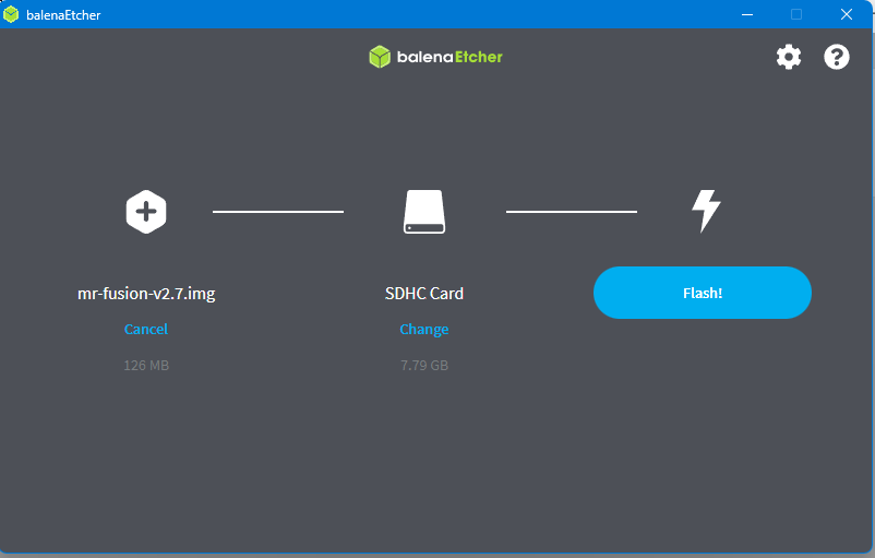
So, if you haven’t yet, remove the SD Card and put it into your favorite PC. I like to use balenaEtcher, so I grab that and the latest Mr. Fusion release (at time of writing, 2.7), and let the etcher do its thing.
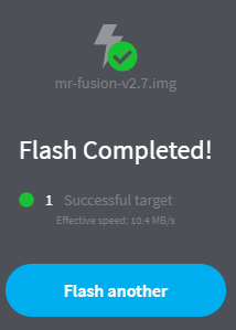
Putting this back into the MiSTer (the MicroSD card slot is on the bottom side of the Nano board, so you should make the gold contacts of the MicroSD face UP when you slide it in), we’re now finally ready to boot this thing up and configure some of the software.
First boot
If everything has gone okay (and why wouldn’t it, things never break or go wrong, right?), you’ll see this on your monitor:
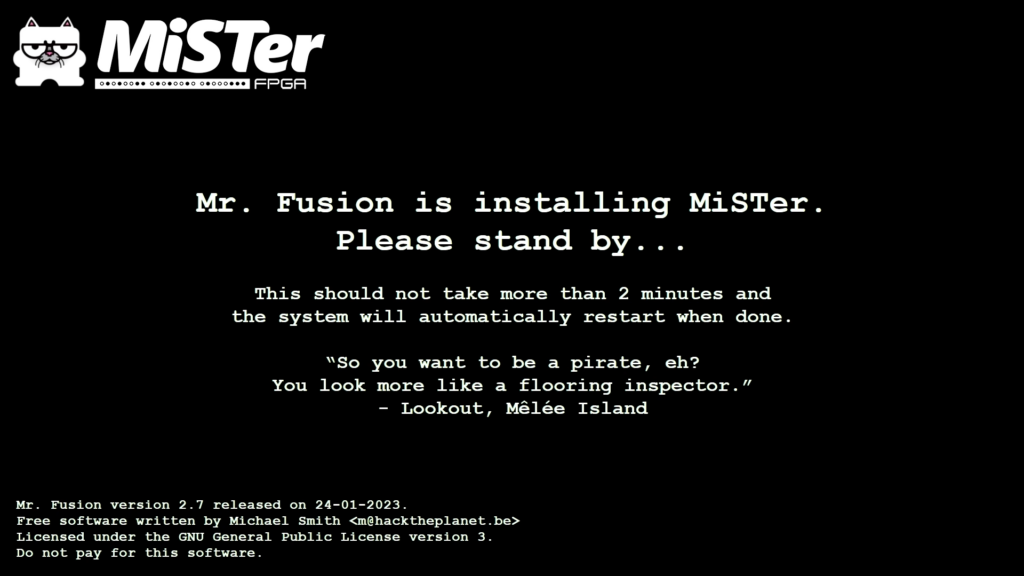
This will reboot, and then come to a screen that at first, made me think the flashing didn’t work right. I didn’t know what to expect, so don’t be alarmed, and in fact, you should expect see this:
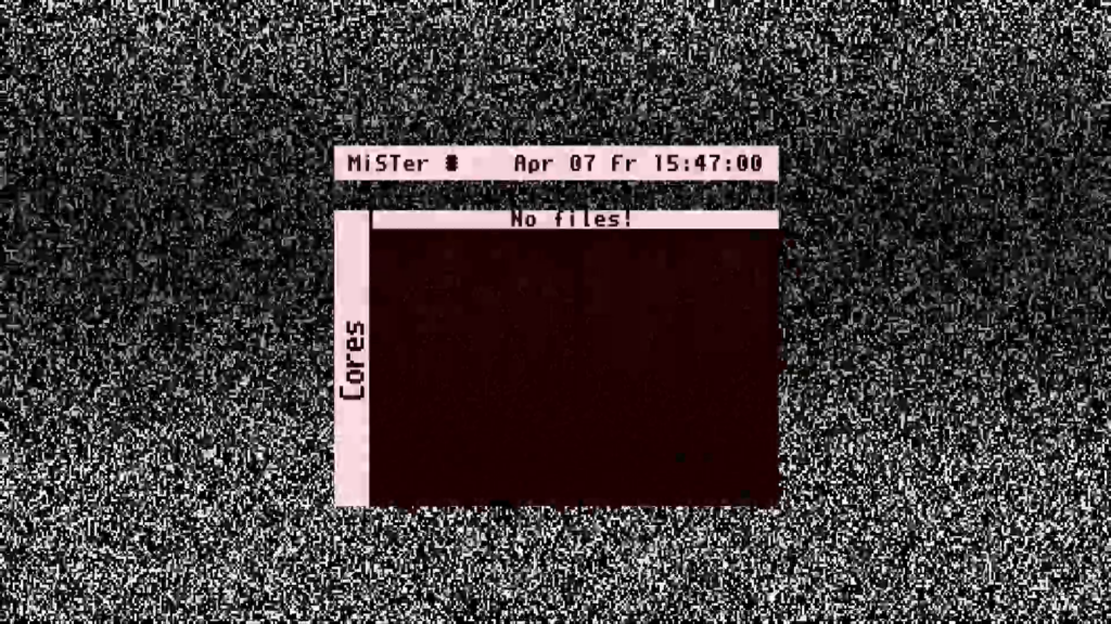
All this means is that you’ve loaded up Mr. Fusion and are looking at a blank core menu because, well, the initial flashing doesn’t install any cores. We’ll have to do that ourselves in a bit. First things first. Connectivity. Well, one more thing first. If the flashing static background starts annoying you, hit F1 on your keyboard to change it. This also easily screws up encoding, as I was streaming his at the time and all of the static made the rest of the stream overlays pixelate.
Initial Network Connectivity
If you’re hard wired in, you should already have an IP address. If not, you should hit Escape, which will bring up the system settings, and select the ‘Scripts’ directory.

At the warning, type yes (since you do want to run the script), and select ‘wifi’ and hit return. Assuming you have a wifi dongle plugged in (and if not, you should just go hard wired with ethernet), you’ll see the list of SSIDs – select yours and enter your password. After that point, you should get taken back to the main menu, but you’ll have a little ‘Wifi’ signal icon in the upper bar of your menu now.

Now we’re cooking. Next steps are to download the well known ‘update_all’ script (not the stock update script that comes with the install – which definitely works if you only want to use that) that downloads all the stuff that the update script does, as well as a lot of neat and/or experimental features should you desire it and performs general updates and downloading of additional scripts. But first let’s go over where I’m storing all of the files the downloader is going to download.
MiSTer file paths and network mount considerations
MiSTer FPGA has a fairly standard directory structure it uses to look up files, be it cores or roms. Whether it’s network storage or the SD Card itself, MiSTer mounts a well known directory structure referenced here: https://mister-devel.github.io/MkDocs_MiSTer/cores/paths
to do any of the following, we need to login via SSH to our running MiSTer. To see these directories in action, you can use PuTTY to open up a terminal into your MiSTer. The default account is root and the default password is 1. (So… maybe we’ll change that later)
After you login, know that all of the directories MiSTer is going to care about are under /media. The basic key directories are:
| /media/fat | The root of your SD Card. If you were to shutdown the MiSTer and mount your card in your windows machine, the contents of that card would be here. |
| /media/fat/_Arcade | Arcade cores go here. Cores are the systems, not the games, remember. |
| /media/fat/_Computer | Computer cores go here. These are things like the Apple II, Commodore 64, etc. |
| /media/fat/_Console | Console cores go here – Nintendo, Genesis, etc. |
| /media/fat/config | Configuration files – generally for each core as you modify and save configurations. |
| /media/fat/games | These are where all your games go. Generally subdirectories under here line up with cores, so /media/fat/games/c64 would be where you put your C64 disk/cart/program images. |
You won’t have some of these directories yet because we haven’t downloaded anything with the update_all script yet (you’ll at least have a Scripts directory because we’ve already run files from there). Previously I mentioned that I did NOT want to constantly remove the MicroSD card to add content to my MiSTer. I would think most people don’t want to do this, especially with a case because getting those SD cards in and out easily is annoying. So, I figure I had these options:
- Use the SD card for primary storage, let the update_all script download cores to the SD card, and use SCP/SSH to transfer files to the MicroSD card to my computer. Doable, but slightly cumbersome
- Use a USB Stick (which the MiSTer should automount according to the core paths page referenced in the github link above. Here we can at least windows to do a little easier transfer, but we still have to move the stick between files.
- Use a Samba share – You can enable the Samba (Windows file share) service on the MiSTer and expose your SDCard over the network as described here: https://mister-devel.github.io/MkDocs_MiSTer/setup/games/ Also doable, but I prefer to not really use the SDCard except for booting up the MiSTer and storing some configuration data.
- Use the CIFS mount scripts and download all cores and games onto my Synology NAS, and then have MiSTer mount those directories instead (even thinking it’s /media/fat, when it’s really talking to my NAS). I liked this because virtually all files are on my NAS, so I can use that from windows more easily than SFTP, and I’m not constantly writing to the MiSTer SD Card. This is the option this document will describe further down below.
So, my goal is to create a NAS share, and have MiSTer mount the FPGA directories for cores, systems, etc. on the NAS, but making it think it’s still under /media/fat (reason being if anything we ever install assumes /media/fat is used, it will just work). The primary directories we’ll leave on the SD card itself are /media/linux and /media/config, which are much more towards MiSTer even running things properly. The cores and games, however, will live on my NAS.
So I created a share and made a dedicate user for it, this way it wasn’t going to see any other directories on the NAS and things are neatly organized. For the CIFS mount to work, the directories must already exist, so I created the directories I needed by using a template.zip file from a forum thread I found on doing this exact thing, referenced here. However, I found I needed to add a couple of directories to that template, so I’ve created my own, which you can grab here. It’s just a zip file with empty directories to get you started. All I did was just unzip it to the root of my NAS MiSTer share.
This zip is a bunch of empty directories you unzip to the root of your NAS share dedicated to your MiSTer FPGA. These directories should exist on the NAS share so when you run the cifs_mount.sh script, your MiSTer will see those /media/fat/ subdirectories, but they’ll actually point to the NAS and not your SD card.
(The reason we do this is that those directories must exist to mount them on the MiSTer, otherwise when the download runs it will download files to the /media/fat/games directory on the SD CARD, not the network mount that we want. We’re using CIFS to trick MiSTer into thinking /media/fat/games is on the SD card when it’s really on the network, remember.)
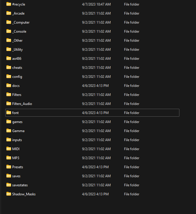
These are the empty directories included in the zip file. (Ignore #recycle, that’s from my Synology NAS)
Download and configure the CIFS_MOUNT scripts
Now that we have those directories created, we need to tell the MiSTer how to mount them. To do that, we’ll download to our /media/fat/Scripts directory (which will NOT be part of our NAS) the two scripts cifs_mount.sh and cifs_umount.sh from https://github.com/MiSTer-devel/Scripts_MiSTer.
cd /media/fat/Scripts
wget https://raw.githubusercontent.com/MiSTer-devel/Scripts_MiSTer/master/cifs_mount.sh
wget https://raw.githubusercontent.com/MiSTer-devel/Scripts_MiSTer/master/cifs_umount.sh
Now, in that same directory, we need to create a cifs_mount.ini file. Here’s mine, you’d obviously use a real IP address for your NAS, a real username, and real password.
# NAS IP (If server name doesn't work, use IP)
SERVER="192.168.50.10"

#The share name on the NAS
SHARE="mister"
USERNAME="mister"
PASSWORD="mister"

#Local directory/directories where the share will be mounted.
LOCAL_DIR="*"

#mfsymlinks most likely is necessary so the update_all ArcadeOrganizer download works.
ADDITIONAL_MOUNT_OPTIONS="vers=3.11,mfsymlinks"

#"true" in order to wait for the CIFS server to be reachable;
#useful when using this script at boot time.
WAIT_FOR_SERVER="true"

#"true" for automounting CIFS shares at boot time;
#it will create start/kill scripts in /etc/network/if-up.d and /etc/network/if-down.d.
MOUNT_AT_BOOT="true"

#========= ADVANCED OPTIONS =========
BASE_PATH="/media/fat"
#MISTER_CIFS_URL="https://github.com/MiSTer-devel/CIFS_MiSTer"
KERNEL_MODULES="md4.ko|md5.ko|des_generic.ko|fscache.ko|cifs.ko"
IFS="|"
SINGLE_CIFS_CONNECTION="true"
#Pipe "|" separated list of directories which will never be mounted when LOCAL_DIR="*"
SPECIAL_DIRECTORIES="config|linux|System Volume Information|#recycle"
You can see in the SPECIAL_DIRECTORIES section we ignore config and linux, which we’ll always want to leave on our SDCard for stability. The rest of the directories are mounted from the NAS IF they exist on the NAS already.
So, saving that file, my scripts directory now looks like this:
/media/fat/Scripts# ls -l
total 160
-rwxr-xr-x 1 root root   911 Apr  6 00:18 cifs_mount.ini
-rwxr-xr-x 1 root root 12993 Apr  6 00:17 cifs_mount.sh
-rwxr-xr-x 1 root root  1051 Apr  6 00:17 cifs_umount.sh
-rwxr-xr-x 1 root root  4662 Jan  1  1980 update.sh
-rwxr-xr-x 1 root root 10638 Jan  1  1980 wifi.sh
I then invoked the ./cifs_mount.sh command to make sure it worked, and voila, here was my output:
./cifs_mount.sh

And now, all of these new directories appear on /media/fat (but most of them are on our NAS!)

Now, if you’re ever unsure as to whether or not the directory you see under /media/fat is local to the SD card or not, check out the mounts by doing a cat /proc/mounts. You’ll see output like this:

You can see all of the directories that are actually mounted to the NAS. These are the same directories our update_all script is going to download to (as well as config/linux/Scripts, but those stay local on the SD card because we’ve either ignored them or did not create a matching directory on the NAS).
You should be able to reboot your MiSTer and SSH into it again and see these mounts are still there.
Download and run theypsilon’s update_all.sh script
Finally, the moment we’ve all been waiting for… let’s get things updated and downloaded.
SSH back into your MiSTer if you rebooted, and in the Scripts directory download the update_all.sh script from theypsilon’s git hub.
cd /media/fat/Scripts
wget https://raw.githubusercontent.com/theypsilon/Update_All_MiSTer/master/update_all.sh
Then, execute it. The update_all.sh script takes a while to run – you may want to run it from the OSD on the MiSTer, or you can still run it via SSH if you prefer. On the MiSTer OSD you’d see this (Hit ESC to get to the System Settings menu, then select Scripts):

Select update_all and you’ll be greeted with a preamble. If you want to use default download options, just let it go, otherwise, hit UP ARROW and you can configure to download optional items. (If you’re on Wifi, this may take a while, might be best to do an initial update via ethernet cable)

I hit UP and was greeted to the main settings page. Where I enabled this and that, but regardless it’s going to download the primary cores, scripts, and folder setup structure for /media/fat/games.

You can always just take the defaults, ‘Exit and Run update all’, and run it later if you want to download Disabled items.
That runs for a looooooong time.
At the very end of the script, barring any issues, you’ll see this:

Your MiSTer will now reboot, and we’re done with the initial downloading. If you look at your NAS share now, you’ll see it holds plenty of files and takes up a bit more space:

Rebooting and final touches
A note on starting up your MiSTer now that you’re mounting a bunch of folders on your NAS: Now that you’re ‘tricking’ MiSTer into thinking /media/fat/<some of your directories> are local and not on the NAS, you may be occasionally surprised if you menu under ‘Arcade’, ‘Console’, or ‘Computer’ is empty when you first start up. Don’t be. Just go back to the root of the menu (hit that OSD button on your case, or just escape out), wait a tick for the cifs_mount.sh script to finish in the background, and then you’ll see your cores and games visible. It’s just on the initial boot up, and usually only takes a few seconds after the menu shows up.
Once that was all said and done, I went to the Scripts directory again and executed the timezone script to set my timezone properly.
Now, that pretty much concludes this round documenting my initial setup. Some good reference links:
HotKeys: https://mister-devel.github.io/MkDocs_MiSTer/basics/hotkey/
Defining GamePads: https://mister-devel.github.io/MkDocs_MiSTer/setup/controller/
MiSTer FPGA Documentation: https://mister-devel.github.io/MkDocs_MiSTer/
MiSTer Wiki on GitHub: https://github.com/MiSTer-devel/Wiki_MiSTer/wiki
SMB/CIFS Mount Threads: https://misterfpga.org/viewtopic.php?t=3246&start=30https://misterfpga.org/viewtopic.php?t=4972
theypsilon’s Update_All_MiSTer repo: https://github.com/theypsilon/Update_All_MiSTer
