- -> The ‘Working’ Commodore 64/128 Diorama and Raspberry Pi VICE Emulator
- Installing the VICE Commodore Emulator for Console Mode on a fresh Raspberry Pi 4
- Mirroring Raspberry Pi HDMI Video to a ST7789 1.3 inch LCD Display
- Patching the VICE emulator to light up floppy drive LEDs
Last Updated on October 6, 2020.
A little bit of backstory: It’s 1985 and the Nintendo Entertainment System begins its assault on North American wallets in the late fall season. As a child of the 1980’s, I was ready and willing to throw my parent’s savings towards the Nintendo firing lines. The problem was, Dad was an unwilling partner.
10 Year Old Me: Dad, I want a Nintendo!
Older, Wiser Father: Well, Son, I bought you this Commodore 128 Computer instead.
10 Year Old Me: God damn it, Dad (internal dialogue).
There went my hopes and dreams of having a Nintendo – replaced with this many keyed Commodore paperweight. Dad’s goal, unbeknownst to me, was simple – get something that could play games but could also be used to learn about computers. One day I was bored enough to pick up the manual…
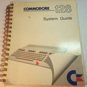
It’s time to open this up.
I don’t remember which exact program I first built – but I do recall it was making use of the Commodore’s sprite mechanisms – some extremely crude animations and graphics manipulation. Of course, most of the time with the Commodore 128 was spent in it’s ’64 mode’, where almost all of the software library resided.
Nevertheless, thanks to my Nintendo-dodging father, I knew exactly what field I was going to get into in some way, shape, or form, by the time I was eleven. I never had a console beyond the Atari 2600 until I was in my late thirties.
Fast forward through the years and Dad’s ‘spare room’ (or ‘pit of crap’ according to my mother) became the ‘computer room’ as far as I was concerned. Now, in the present, I want to pay homage to that era with a diorama capturing the spirit of that back room. I also wanted to play some of those old games again, along with games I never knew existed at the time.
Birth of a diorama / emulator combo
I’ve put together Raspberry Pi emulator setups before, and I wanted to create one for myself, and I wanted to use this to specifically target my Commodore days. While you’ll see a model of a Commodore 128, anybody who really used one will tell you it spends most of it’s time in ’64 mode’ since it was backwards compatible. So the first thought was a 3D printed case that looks like a Commodore computer to wrap around my Raspberry Pi.
I found a few models online on sites like Thingiverse, an example being this one.
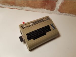
I liked the idea, but I thought maybe I could add something to it – like LEDs? A monitor? A 1541 disk drive to hold an SD Card? This will run the popular VICE Commodore emulator, so I figured a retro case like this to display the Raspberry Pi 4 I was planning to use would be a cool little project to take on. Unfortunately, my brain wasn’t going to let me get off that easily.
My brain goes down a creative spiral.
If I’m going to print a case and a little disk drive, why not a monitor? Instead of that, what about a little computer desk and smaller versions of those components? My mother does 1/12th scale miniatures (1 inch = 1 foot) as a hobby, so I just naturally went with that scale. The more I thought about it, the more I realized trying to rebuild the Commodore setup I had as a child was really the way to go. We (sadly) sold those pieces long ago; I felt building a diorama that captured the spirit of that room was now my goal.
Now I know I’m building a ‘room’, what about those LEDs? Could I incorporate some simple little power LEDs into each component – monitor, disk drives, and keyboard?
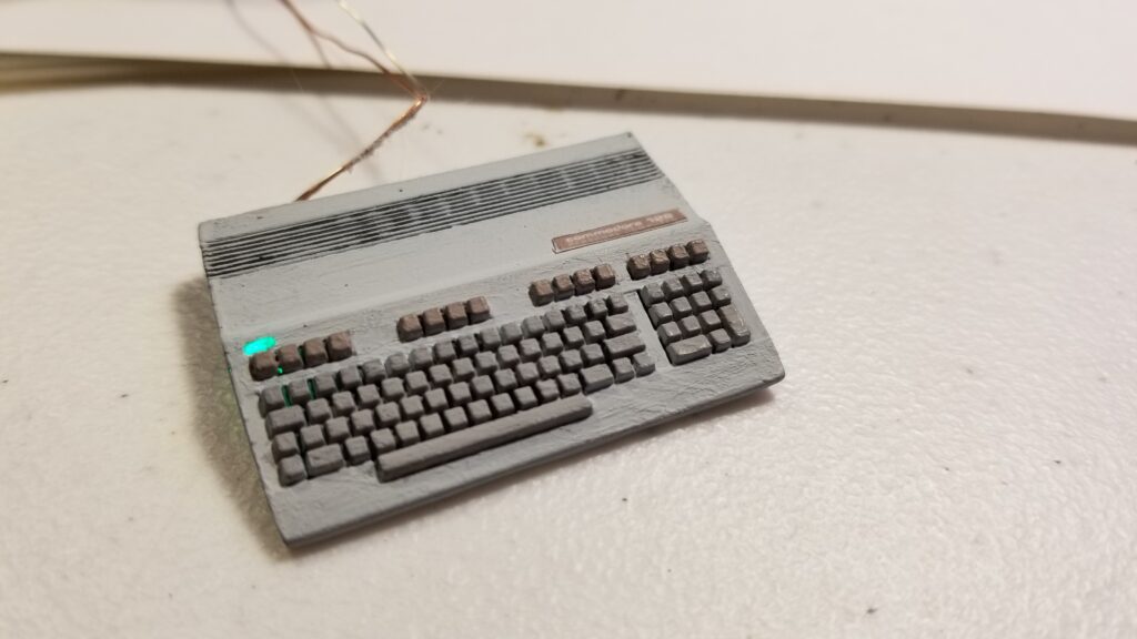
If I’m going to build and/or manipulate 3D models to house LEDs for power – what about disk drive activity? Could I have the classic red activity light on a 1541 disk drive turn on when the VICE emulator loads ‘virtual’ floppy disk data?
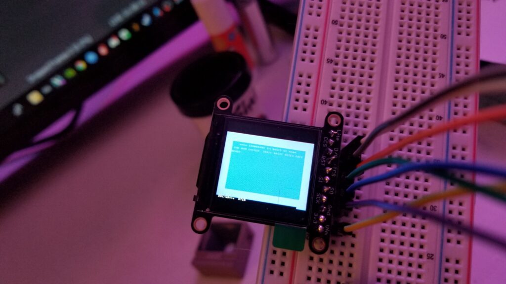
If I’m going to manipulate power and activity LEDs for the components… what about a tiny LCD screen inside the Commodore 1802 monitor? Could I play animations? Show the ‘READY’ screen? Could I even mirror the Raspberry Pi output?
If I’m going to do all that, I should get some sort of Commodore styled keyboard of some sort to type with so I can use those special PETSCII keys.
The VICE emulator also had some special keys for those common emulator functions, like mounting a virtual floppy image, pausing the emulator, loading/saving emulator machine state, etc. Maybe I could build a little ‘mini-macro’ keyboard to shorten those keystrokes.
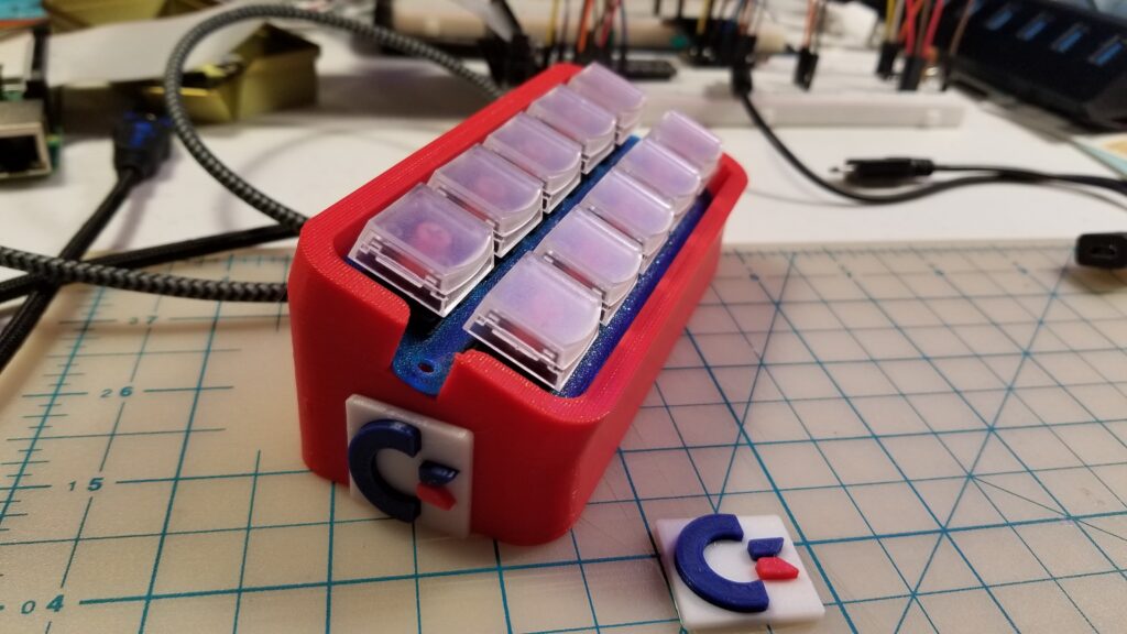
I had a few other design ideas that went farther, but this is where I stopped. If I went too far, I knew I’d never get it done. Nevertheless, that was my thought process behind the diorama / emulator combo. I wanted to pay homage to that era as well as have a working emulator.
The Diorama is still a ‘room’
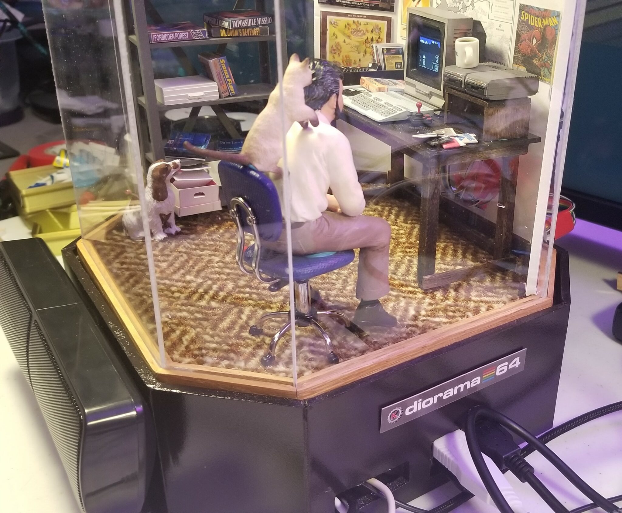
My mother has been creating miniatures for years now – primarily 1/12 ‘dollhouse’ scale. Once I mentioned the idea of the diorama to her, her ‘miniature brain’ (ahem, don’t read that literally) went to work and she built the structure for the room box, carpet, desk, shelves, and even the old rolling chair we had plus some family pets. It really started to feel like this diorama would capture the spirit of the computer room of my youth. What I wasn’t expecting was mixing some ‘old me’ and ‘young me’, as she found a figure, and with some paint in the right spots, created… mini-me.
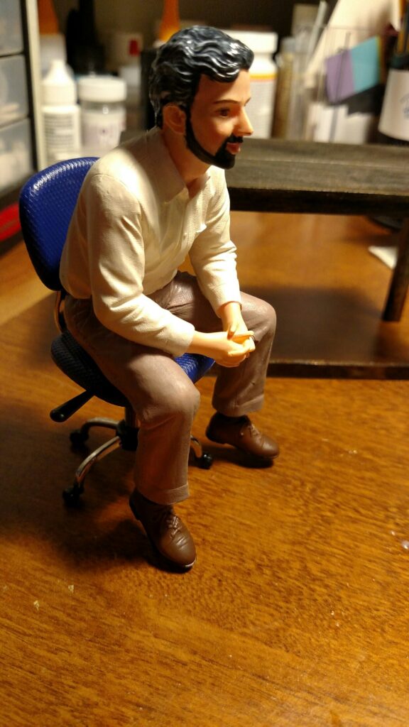
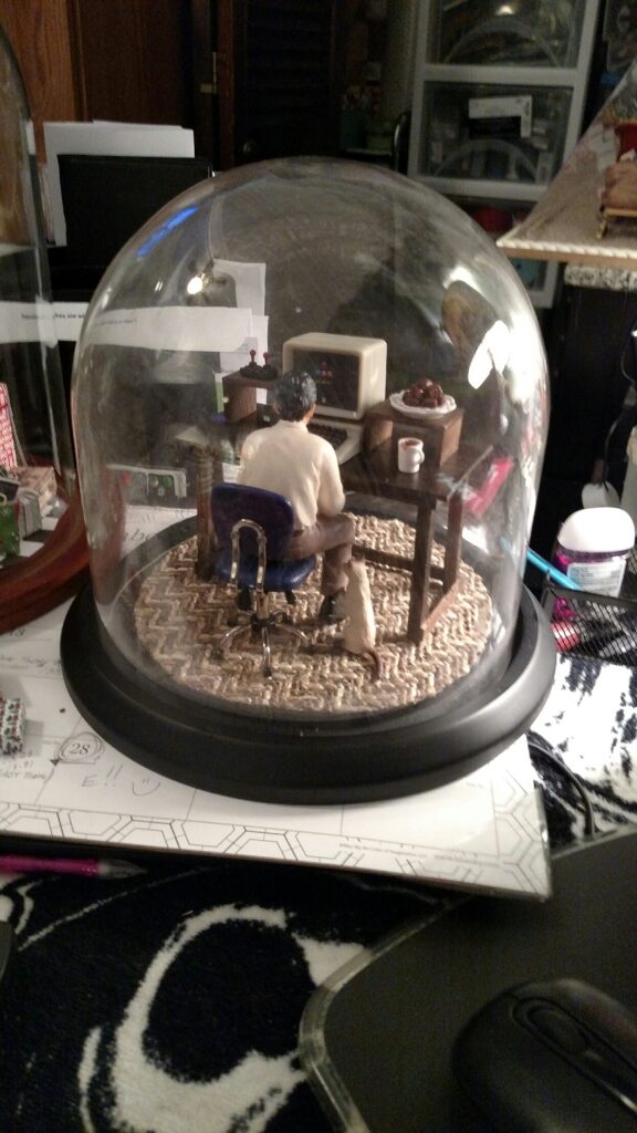
She created her own prototype of the diorama with a domed room, with myself and my Siamese Luna enjoying what little air is left under this glass by playing some Pac-Man (which I’d be replacing with Commodore specifics).
Making The Mini Commodore Parts
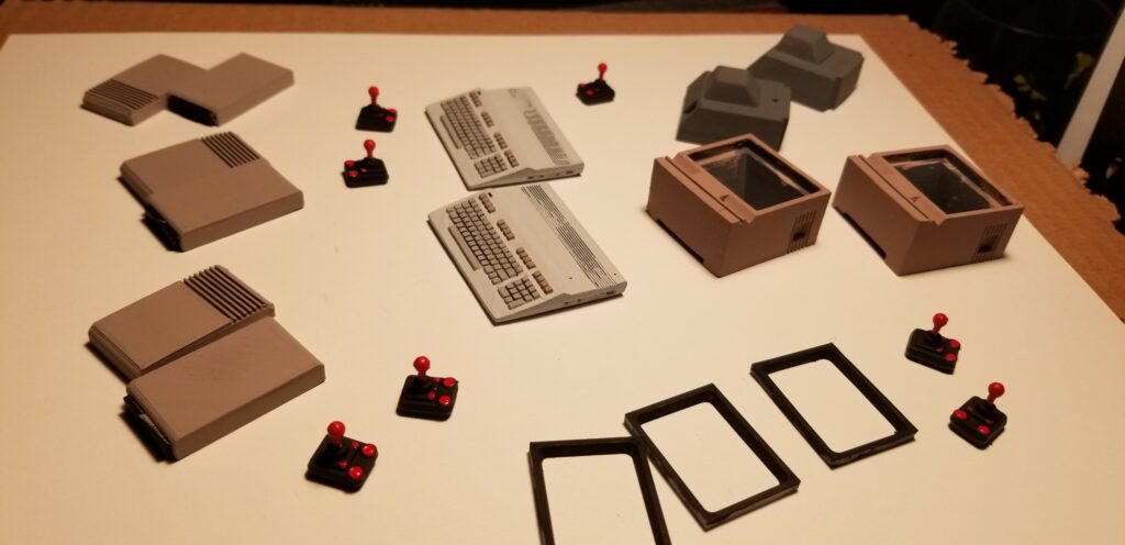
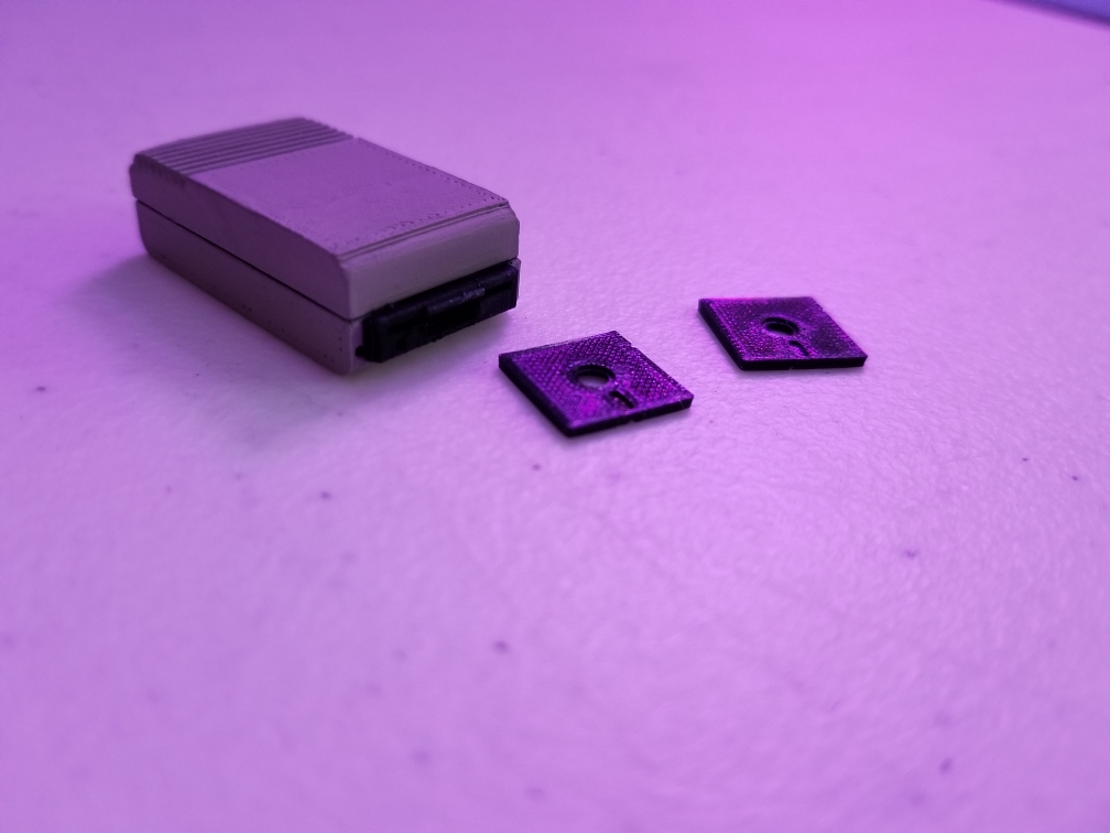
Taking a few models from Thingiverse (the series article on the modeling will have the details), and modifying them for some future LED wiring, I went to work recreating the system we had – A Commodore 128, two 1541 drives, and a monitor. I also went about creating some floppy disks which you can see below, though I ended up making them thinner later.
After slimming down those floppies I created envelopes resembling some of the makers I remembered from my youth – Commodore branded floppies, BONUS, Elephant, Maxell, and Verbatim. You may also recognize an EA branded floppy envelope from the days where EA was ground breaking and universally adored.
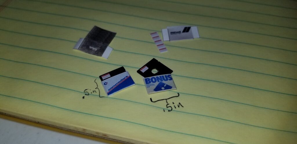

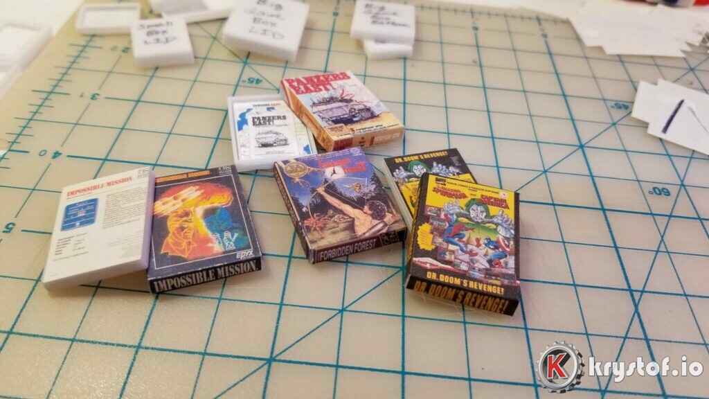

A ‘living, breathing’ Commodore.
The LED related goals of the diorama: Power LEDs and drive activity LEDs that match our VICE emulator install. When you load a virtual floppy in VICE, I want the drive 8 LED to light up. That requires a customization we’ve made to VICE itself (details in the series article), but it all has to come together connecting to the Raspberry Pi, a custom circuit board, and power. Needless to say, the breadboard came in mighty useful during this endeavor.
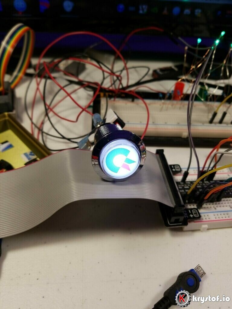

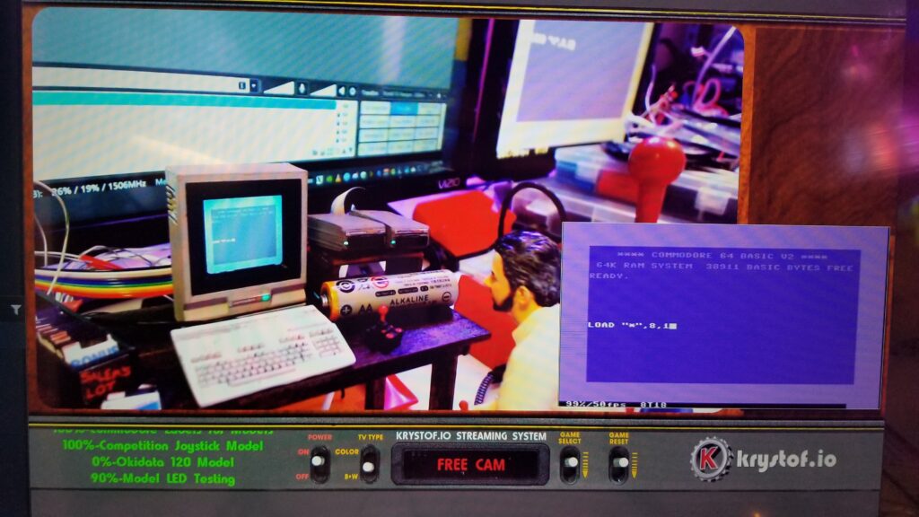
Also, I wanted the 3d printed monitor to work as an enclosure for a small LCD that mirrors the HDMI output of the Raspberry Pi – here’s the initial capture I took when it somehow didn’t melt upon plugging all of it together:
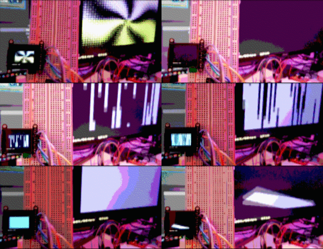

Twitching The Progression
I decided to clean up the work space a little bit and get the Twitch stream going. Figured I’d work on this and if anyone decided to stop by and chat about it, they could. In fact, they did. So far I’ve met a few interested in the old Commodore retro scene, some more on the electronics side of the circuit, and some just curious as to what the hell I’m doing.

Diorama/Emulator Parts Breakdown
This diorama / emulator combo breaks down into these major components, and thus the series articles for more detail follow this list. As I wrap up each one I’ll post the links here for posterity.
- Raspberry Pi 4 – The heart of the electronics – this runs the emulator as well as drives the circuit controlling power and drive activity LED’s. You can now see more on the VICE and OS install here: https://krystof.io/installing-the-vice-commodore-emulator-for-console-mode-on-a-fresh-raspberry-pi-4/
- LCD display – this mirrors the Raspberry PI’s HDMI output, so as the big-me plays games, the mini-me in the diorama is playing the same game – or is it the other way around?
- LED circuit board – This reads GPIO pin inputs from the Raspberry Pi and switches on the power and drive activity LED’s. I also decided to try out a simple ‘Power’ button to ease the shutdown of the Raspberry Pi.
- 3D Printed Commodore Models – Modified and scaled accordingly, printed in resin or filament, and painted by hand (crap-fully)
- Custom VICE build and LED driver software – I created a custom VICE build to get my hook into the floppy drive activity and get that state sent to the LED circuit – so when VICE considers a floppy drive active, my LED circuit turns the LED on or off accordingly.
- Diorama Room containing models of our old computer desk, floppy disk holders, game boxes, and wall art I would hang in the computer room or my bedroom over the years.
- Input Peripherals – I need a keyboard to type on and joysticks to … joy with.
- Custom Keyboard Deck – This keyboard of 10 keys controls common emulator functions (mount floppy image, pause, restart emulator machine, etc.)
- Diorama case ‘base’ – where we’re going to store the electronics of this diorama/emulator combo – underneath in a 3 inch tall base for the diorama to rest on.
There are some parallel threads in the series here – I worked on many pieces at the same time – and you could to if you were recreating it. Nevertheless, here’s how the series is presented – and I’ll do my best to keep this cohesive.
Series Breakdown
As I upload articles and videos, this list will be updated and links created. Stay tuned!
- This entry – the overview and motivation – Released Jan 4 2020
- VICE on the Raspberry Pi 4 Install – Raspberry Pi 4, VICE Compiling – Released Jan 12 2020
- Raspberry Pi 4 and ST7789 LCD Install – How to get frame buffer copying and display rotation working. – Released Jan 19 2020
- Custom VICE build and Python Shared Memory – Using Linux shared memory to communicate between VICE and Python to drive the proper drive activity LEDs – Released Feb 15 2020
- Controlling LEDs from a Raspberry Pi and a Darlington Array – Isolating the power driving LEDs and building the LED circuit
- 3D Modeling the Commodore Computer – Modifications to support LED housing and wiring, painting, and decals
- Input Peripherals – Keyboard and Joysticks and some alternate considerations
- VICE Custom Keyboard Deck – Using an Arduino compatible Teensy to act as a USB HID Keyboard
- Diorama Room – It’s not a diorama without some background items and finishing touches.
- Diorama Case Base – Final touches and assembly of the diorama.
- Retrospective – Looking back as we moved forward through this series.

Impressive detail + functionality! Very inspiring indeed, congratulations!
Thank you, comm64!
Remarkable
Thanks, Ben!
I’d love to read the rest of this! How have you gotten on?
Thanks, jcar! Well, while the diorama is complete, I’m taking some time on the articles – I’m building a replica of that diorama’s circuitry with a slighly cleaner design, primarily because there are too many jumper cables and such. I’ve diagrammed it out and I’m dusting off the soldering skills to see how it works. Once I can get that done I’ll continue the articles so I can present some of that work in a more consumable format as opposed to just some pictures of my rats nest of wires in the first prototype. 🙂
We’ll get there eventually!
Very nice! Wish you had gone with a different design for the monitor. The 1084 or 1902 perhaps. Cheers!
Ha! Thank you! Nostalgia drove me to that one, I have that monitor sitting behind me on a shelf, as inferior as it might be compared to the 1084 or 1902! 🙂