- The ‘Working’ Commodore 64/128 Diorama and Raspberry Pi VICE Emulator
- Installing the VICE Commodore Emulator for Console Mode on a fresh Raspberry Pi 4
- -> Mirroring Raspberry Pi HDMI Video to a ST7789 1.3 inch LCD Display
- Patching the VICE emulator to light up floppy drive LEDs
Last Updated on May 30, 2021.
My Commodore 64 Diorama project was well underway. After installing VICE on the console of a Raspberry Pi 4, the next step was to make sure I could get a tiny display that would fit some sort of ‘tiny monitor’ I’d have to create further into the project. I shopped around a few different places, but I ended up really liking two, both available from Adafruit. Either way, we’re mirroring the Raspberry Pi to a ST7789 driven LCD display.
Previously in the series, we installed VICE on our Raspberry Pi and made sure it worked. Now we want to mirror the HDMI output to our tiny LCD for the diorama.
Here’s our video that covers this article at a high level:
Two LCDs enter, One LCD leaves
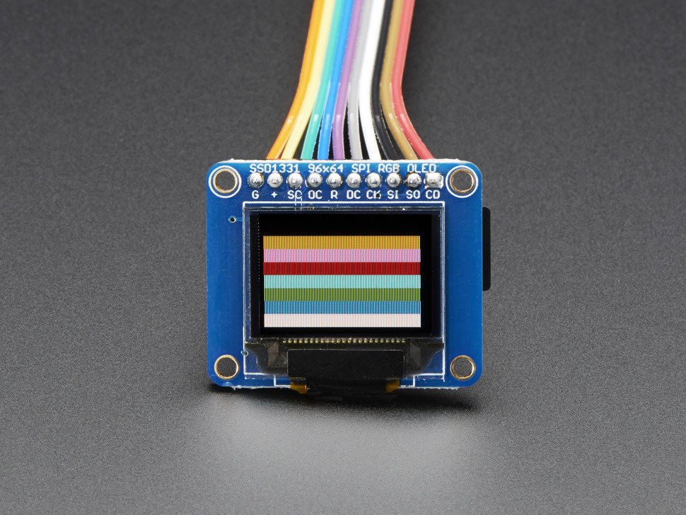
The OLED Breakout Board – 16-bit Color 0.96″ w/microSD holder was a contender. At about 1/12 scale this would have worked out nicely, though it felt a little ‘wide screen’ compared to the monitors I knew of my youth. I was also concerned with resolution, as it supports 96×64, a far cry from the Commodore 64’s 320×200.
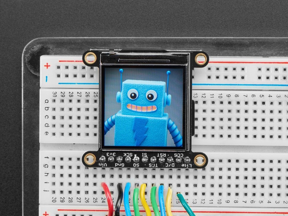
The other, and my ultimate winner – the Adafruit 1.3″ 240×240 Wide Angle TFT LCD Display with MicroSD – ST7789 at least got me closer with 240×240, though it was a touch larger. To that end, I’d try both with the Raspberry Pi and compare. Once I plugged in the 240×240 display and saw the Commodore 64 Ready screen, I was sold. Even though you’d be able to make out what I was playing on the OLED display mirroring my HDMI output, with the 240×240 you can actually read a good amount of text, as well. We have a winner.
A Couple of Quests for the Chosen One
Adafruit has a great page in terms of how to wire this up to an Arduino and Raspberry Pi located here. It’s where I learned that the ST7789 chip is used to drive two different LCD displays – 240×240 and 320×240. This becomes important later as I struggle with getting that working on the Raspberry Pi. Regardless of what display I chose – I knew I needed to have the following requirements satisfied:
- The LCD should mirror HDMI output – I didn’t want this to be the primary display, but a mirrored display.
- The LCD screen needed to be in a specific orientation – pins on the bottom – so they could more easily hide inside the 3D printed monitor ‘bottom’
Wire Before You Fire
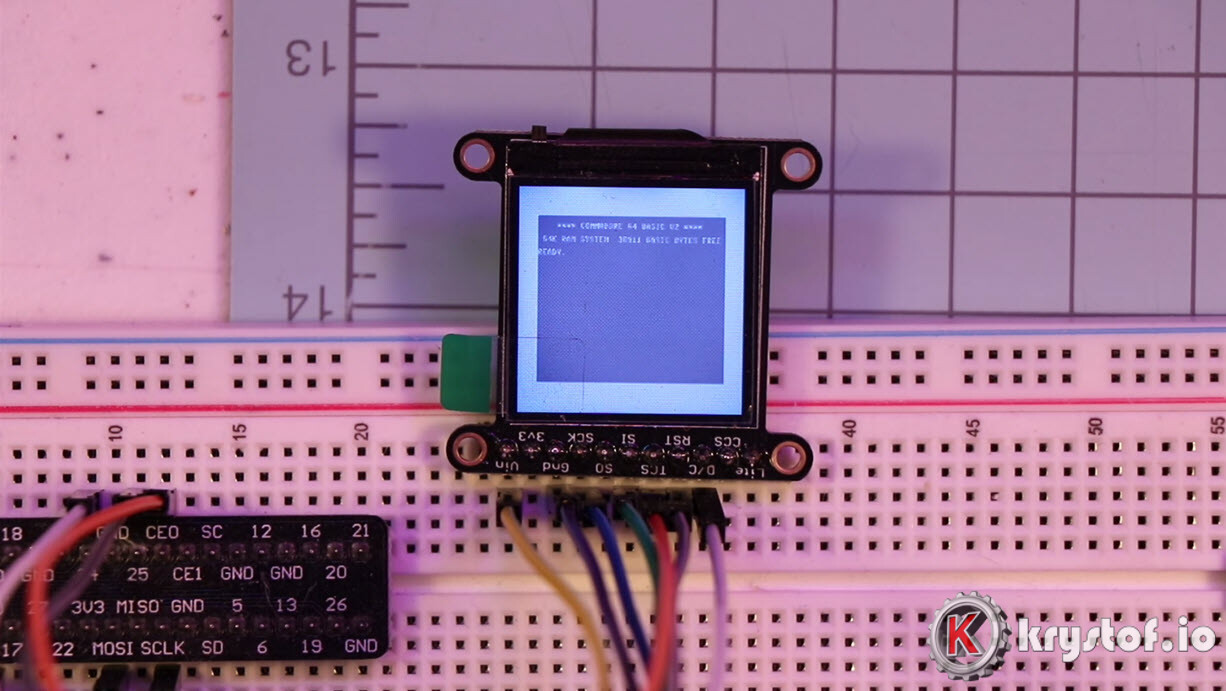
The display doesn’t come with header pins pre-soldered, so after remembering which end of the soldering iron is the hot end, I was able to move forward by placing the display into my breadboard:

I followed the basic Adafruit directions for wiring the ST7789 driven 240×240 display into my Raspberry Pi. Key points:
- This is an SPI mode device. We’re using the Raspi’s SPI0 mode, so that some of the LCD pins need to wire up to specific Raspberry Pi Pins. More on SPI here.
- We have a choice on the LCD’s reset pin, we went with a loose default of 24 on the Pi.
- We have a choice on the D/C pin, we went with a loose default of GPIO 25 on the Pi.
Here’s from Adafruit’s page specific to our ST7789 driven LCD display: (Editors Note – If you compare this to Adafruit’s wiring page, you may notice I swapped my RST and D/C pins – Adafruit uses 24/25 and I’m using 25/24 – It’s fine as long as you’re consistent with your physical pins and the command line options you’ll use later. Thanks, Thomas!)
- Vin connects to the Raspberry Pi’s 3V pin
- GND connects to the Raspberry Pi’s ground
- CLK connects to SPI clock. On the Raspberry Pi, thats SCLK
- MOSI connects to SPI MOSI. On the Raspberry Pi, thats also MOSI
- CS connects to our SPI Chip Select pin. We’ll be using CE0
- RST connects to our Reset pin. We’ll be using GPIO 25 but this can be changed later.
- D/C connects to our the data/command pin. We’ll be using GPIO 24, but this can be changed later as well.
The DC or D/C pin is needed by some devices to distinguish between commands or data for the controler.
Since SPI only pushes out anonymous bitsreams the user code has to “tell” the controler if this will be a command (e.g. D/C LOW) or a data (e.g. D/C HIGH) bitstream. And so D/C is not actually an SPI pin, but this gives you freedom which Core pin to choose.
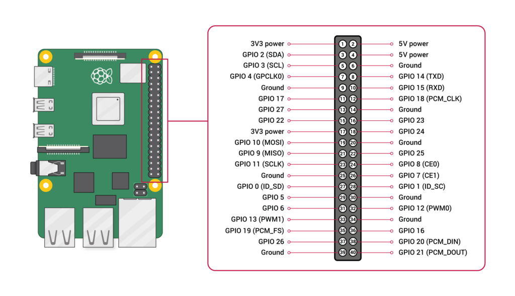
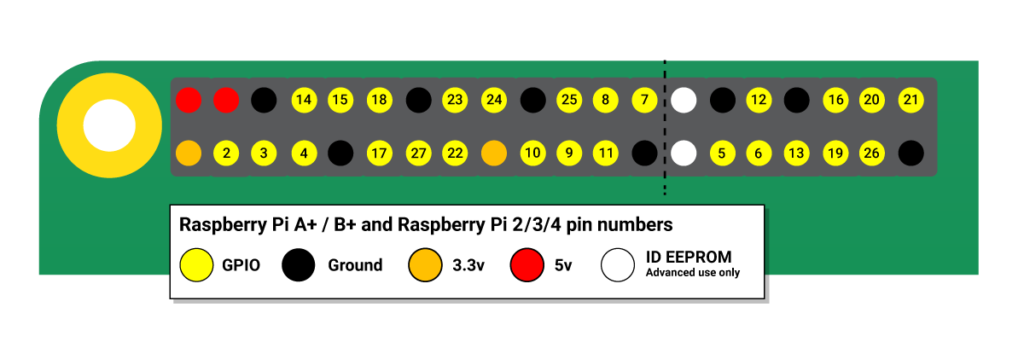
Remember that the Raspberry PI has numerous GPIO pins, but GPIO pin 24 doesn’t mean pin 24 on the pin-out diagram – always refer to some cheat sheet like this one from RaspberryPi.org shown below. Also, another great Raspberry Pi pin-out page that’s interactive is made available by Gadgetoid.
Okay, so we’ve got it wired now, and there’s a promising backlight barely illuminating the LCD when we turn the PI on. We’re one step closer to mirroring our Raspberry Pi to the ST7789 driven LCD Display. Now what?
LCD Driver Powers activate! Form of a mirrored display
While I could have used Python to draw some Commodore images, screenshots, and other static media on the display, I want to actually mirror the display. What shows on the HDMI output should show on the LCD, but I need the mirror scaled. My monitor I’ll play games on doesn’t support 320×240 as a resolution, the bare minimum is 800×600 to make it work well enough. So I searched around the internet and found a couple of solutions that did NOT turn the LCD into the only display or require me to overwrite with a new image.
This is where things might get a little confusing. Both solutions I’m presenting here involve taking the HDMI display output and doing a little frame-buffer copy and manipulation magic.
- Notro’s fbtft LCD device drivers, which create an LCD frame buffer at /dev/fb1, then utilizing tasanakorn’s fbcp program which copies /dev/fb0 (HDMI output) to /dev/fb1 (LCD output), effectively mirroring the display.
- juj’s fbcp-ili9341 display driver that effectively does the same thing as #1, though it doesn’t technically create it’s own framebuffer, and it’s not just for ili9341 displays (it supports my ST7789!)
Which one to use? Well, if only one works for you, choose that one. Otherwise, I found that the second, fbcp-ili9341 worked the best, but it does utilize a little more CPU, so you may very well want to test both (the Raspberry Pi 4 handled it fine)
The primary issues I had with both of these solutions involved rotation. My requirements for either solution were to have the header pins aligned with the bottom of the display so I could more easily hide them in the mini-LCD monitor’s bottom piece.
Option 1 – fbtft and fbcp
The Journey to a working LCD mirror
Notro’s fbtft driver repo seems to be still a good reference point but may not be forever. There’s a lot of discussion around the future of this project, as part of it has been brought into the Linux staging structure, and that it may stay there forever stagnating based on some discussions on the development page. Nevertheless, it did end up working.
There’s a lot of good information to sift through on that wiki, but I’ll keep this page more towards my journey in getting it working.
I saw some references in the staging code base to the ST7789 driver, so it felt promising:
https://github.com/torvalds/linux/blob/master/drivers/staging/fbtft/fb_st7789v.c
Now, the key here is that if these drivers are effectively already part of my Raspbian install, I should be able to use the Linux modprobe commands to load these modules in. By looking at other sample modprobe commands I tried this against my Raspberry Pi with the LCD on the breadboard:
#Screen mirrors but inverted colors and rotation
sudo modprobe --first-time fbtft_device name=fb_st7789v custom width=240 height=240 speed=32000000 gpios=reset:25,dc:24
The command above loads the fbtft_device module with a custom configuration based on the provided driver fb_st7789v. Notice that we didn’t have to declare the standard SPI pins but we need to reference our two custom GPIO pins from the wiring section – reset and dc.
Remember that this command just creates a framebuffer for the LCD at /dev/fb1, it doesn’t actively mirror the display. We need the fbcp program for that. I just run fbcp as a background process and voila. The LCD came to life … but it’s a little off. (Also, don’t worry, the full setup steps are at the end)
Here’s the result when I ran ‘htop’:
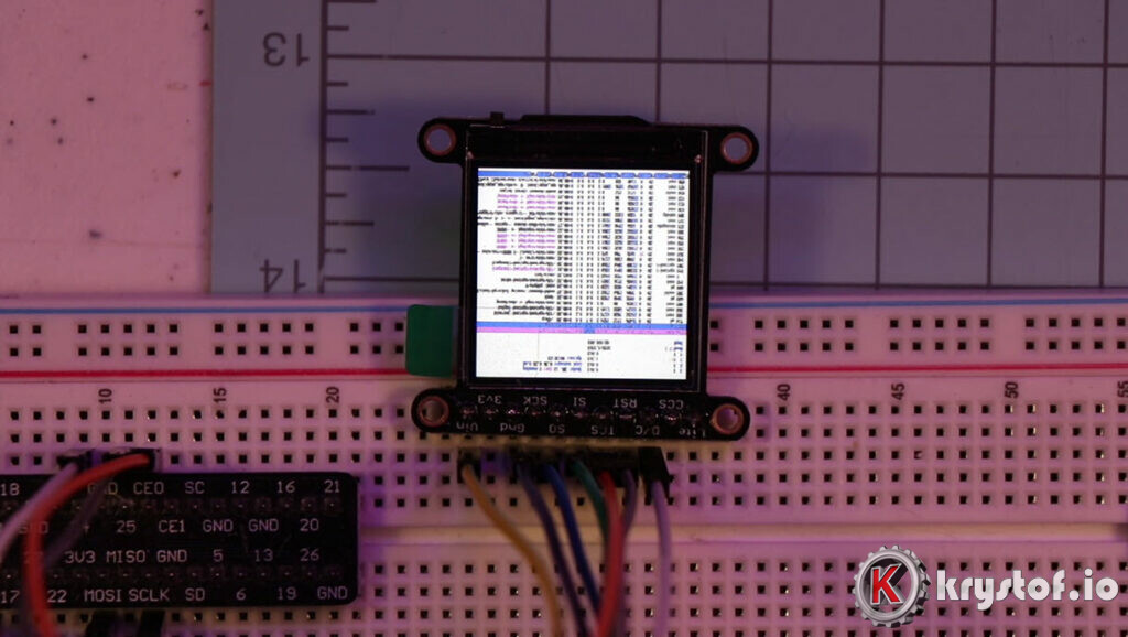

If you don’t know what that should look like, I can tell you that display screen is rotated 180 degrees off my desired layout (pins on the bottom), and the screen color is ‘negative’. It should be a black screen with white text.
Now I’m off to figure out how to rotate and how to invert the colors. I dug around the issues page on the wiki and found this reference:
https://github.com/notro/fbtft/issues/425
Github user tr1p1ea references an init string argument you can also pass along in the modprobe argument, which probably was setting some ST7789 specific codes I needed to set.
init=-1,0x11,-2,120,-1,0x36,0x00,-1,0x3A,0x05,-1,0xB2,0x0C,0x0C,0x00,0x33,0x33,-1,0xB7,0x35,-1,0xBB,0x1A,-1,0xC0,0x2C,-1,0xC2,0x01,-1,0xC3,0x0B,-1,0xC4,0x20,-1,0xC6,0x0F,-1,0xD0,0xA4,0xA1,-1,0x21,-1,0xE0,0x00,0x19,0x1E,0x0A,0x09,0x15,0x3D,0x44,0x51,0x12,0x03,0x00,0x3F,0x3F,-1,0xE1,0x00,0x18,0x1E,0x0A,0x09,0x25,0x3F,0x43,0x52,0x33,0x03,0x00,0x3F,0x3F,-1,0x29,-3What is all this crap? These are initialization parameters you can send directly to your LCD driver chipset. Notro’s page has some information there, but understanding the specifics for your LCD require the datasheet. Nevertheless, I tried it out and we got farther…
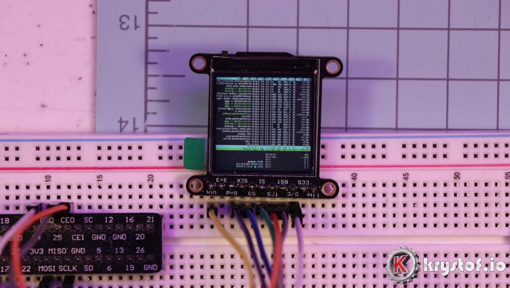

The fbtft_device page on the wiki references other parameters – one of them being rotate:
rotate
Angle to rotate display counter clockwise: 0, 90, 180, 270
Okay, so we rotate with our updated command – I figured 180 degrees to start.
sudo modprobe --first-time fbtft_device name=fb_st7789v custom width=240 height=240 speed=32000000 rotate=180 gpios=reset:25,dc:24 init=-1,0x11,-2,120,-1,0x36,0x00,-1,0x3A,0x05,-1,0xB2,0x0C,0x0C,0x00,0x33,0x33,-1,0xB7,0x35,-1,0xBB,0x1A,-1,0xC0,0x2C,-1,0xC2,0x01,-1,0xC3,0x0B,-1,0xC4,0x20,-1,0xC6,0x0F,-1,0xD0,0xA4,0xA1,-1,0x21,-1,0xE0,0x00,0x19,0x1E,0x0A,0x09,0x15,0x3D,0x44,0x51,0x12,0x03,0x00,0x3F,0x3F,-1,0xE1,0x00,0x18,0x1E,0x0A,0x09,0x25,0x3F,0x43,0x52,0x33,0x03,0x00,0x3F,0x3F,-1,0x29,-3Which now leaves us with something completely different – I thought I saw rotation but couldn’t tell easily – so I ran VICE and saw it fill up only part of the screen!
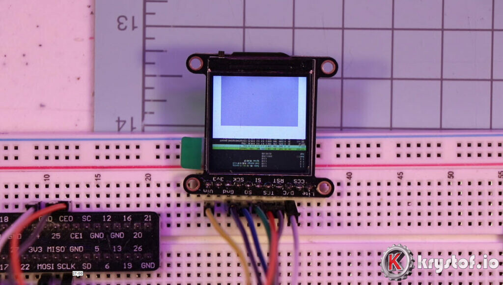

During my research on fbtft and fbcp, I ran across that the ST7789 driver chip supported 320×240 and 240×240 displays. So it looked like to me that my 240×240 lcd was acting as a viewport into the ‘opposite end’ of the video ram that stores the 240×240 image as configured by our modprobe command.
I had a rough idea now of what I was looking for – I need to ‘scroll’ up about 320-240 = 80 pixels. How the **** am I supposed to do this? At this point I started looking for the ST7789 data sheet so I could see if there was some ‘mode’ or related setting. After perusing this for a while, I found something quite interesting in the PDF:
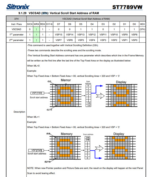

At this point it looked like I wanted to add to our init string. Something with instruction 37h, with 2 parameters. I defaulted the first to zero and the second to the number of pixels I wanted to ‘scroll’. I wasn’t sure if my rotation settings ‘inverted’ the pixel count so I just started with the difference of 320-240 = 80. Of course, we’re dealing with hex, so thats 0x50. The full piece of the initialization string I inserted after the 0x36 instruction follows:
-1,0x37,0x00,0x50
-1 (break for new instruction)
0x37 Instruction for Vertical Scroll Start Address Of RAM
0x00 First Parameter  (defaulted this to 0)
0x50 Second Parameter (set this to 80 pixels, converted to hex)
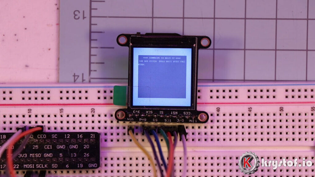
So now my init string, with the extra 37h instruction added, yielded this result:

Install Instructions for Option 1 – fbtft and fbcp
So, we at least have something working. That was the entire goal of this first stage – just get the LCD mirroring the HDMI output of my Raspberry Pi with VICE. Good to go! So let’s finish off option 1 by building the list of instructions.
Since fbtft drivers are already part of Raspbian Buster, all we really need to do is download and copy fbcp, and basing the instructions off that GitHub page: https://github.com/tasanakorn/rpi-fbcp
mkdir ~/fbcp-src
cd ~/fbcp-src

git clone https://github.com/tasanakorn/rpi-fbcp.git
cd rpi-fbcp/

mkdir build
cd build
cmake ..
make
After that point, a new fbcp binary now exists in the build directory we just made.
To just test the general execution of these two, I’ll enter the commands into the shell. Afterwards I’d see the LCD activate and mirror the screen properly.
#start LCD Driver - create fb1 frame buffer
sudo modprobe --first-time fbtft_device name=fb_st7789v custom width=240 height=240 speed=32000000 rotate=180 gpios=reset:25,dc:24 init=-1,0x11,-2,120,-1,0x36,0x00,-1,0x37,0x00,0x50,-1,0x3A,0x05,-1,0xB2,0x0C,0x0C,0x00,0x33,0x33,-1,0xB7,0x35,-1,0xBB,0x1A,-1,0xC0,0x2C,-1,0xC2,0x01,-1,0xC3,0x0B,-1,0xC4,0x20,-1,0xC6,0x0F,-1,0xD0,0xA4,0xA1,-1,0x21,-1,0xE0,0x00,0x19,0x1E,0x0A,0x09,0x15,0x3D,0x44,0x51,0x12,0x03,0x00,0x3F,0x3F,-1,0xE1,0x00,0x18,0x1E,0x0A,0x09,0x25,0x3F,0x43,0x52,0x33,0x03,0x00,0x3F,0x3F,-1,0x29,-3
Then, we need to run fbcp so it can copy the framebuffer from HDMI (/dev/fb0) to the LCD (/dev/fb1) – run this from your fbcp’s build directory you created earlier:
./fbcp &
What if we want this to run on start up? There are numerous ways to do that, here’s a simple one – pop it into rc.local. We’ll cover alternate methods later in the series, this article is just about getting the LCD going.
#Copy fbcp and start it up and the fbtft drivers  (run from your fbcp build dir)
sudo cp fbcp /usr/bin
sudo chmod +x /usr/bin/fbcp

sudo nano /etc/rc.local
Add the following lines to rc.local before ‘exit 0’. Remember the sudo modprobe is all one single line.
sudo modprobe --first-time fbtft_device name=fb_st7789v custom width=240 height=240 speed=32000000 rotate=180 gpios=reset:25,dc:24 init=-1,0x11,-2,120,-1,0x36,0x00,-1,0x37,0x00,0x50,-1,0x3A,0x05,-1,0xB2,0x0C,0x0C,0x00,0x33,0x33,-1,0xB7,0x35,-1,0xBB,0x1A,-1,0xC0,0x2C,-1,0xC2,0x01,-1,0xC3,0x0B,-1,0xC4,0x20,-1,0xC6,0x0F,-1,0xD0,0xA4,0xA1,-1,0x21,-1,0xE0,0x00,0x19,0x1E,0x0A,0x09,0x15,0x3D,0x44,0x51,0x12,0x03,0x00,0x3F,0x3F,-1,0xE1,0x00,0x18,0x1E,0x0A,0x09,0x25,0x3F,0x43,0x52,0x33,0x03,0x00,0x3F,0x3F,-1,0x29,-3

#
#Add a little sleep before starting fbcp to allow fbtft to initialize
#(your display might stay blank otherwise)
#
sleep 2

/usr/bin/fbcp &
Reboot and you should see the screen mirror after the boot process initializes some. If you don’t have your HDMI output active, VICE may not load (it doesn’t get a good hook into /dev/fb0) – so you may need to edit your /boot/config.txt and add:
hdmi_force_hotplug=1Option 2 – fbcp-ili9341
A faster alternative to fbtft/fbcp that uses a little more CPU
I was initially happy with option 1 – I wasn’t planning on playing games using the tiny LCD, just mirror it so the diorama looked alive. However, I still perused a few other search threads and found out about this other option called fbcp-ili9341, and while the name may be confusing (it doesn’t create a framebuffer, and it’s not just for the ili9341 driver), I was able to get it working with our ST7789 1.3″ LCD display.
Why did I try it out? Turns out, SPI doesn’t have the inherent bandwidth as it stands with libtft and fbcp – and since I’m playing games, which inherently implies video as opposed to text, I noticed the refresh rate on the LCD was always a little stuttered while playing C64 games and demos. Through some optimizations and shortcuts, the author juj has created an alternative that is faster than our option 1, all the way to 60fps. Ohhhhh yeah.
So here’s the journey to making that work. A little easier, and a bit nicer payoff. This option, while using a little more CPU (Our Raspi has 4 cores, so it’s not a big deal), is fast. In fact, it says so on it’s GitHub page, so you know it’s true!
Since the name is also confusing, here’s why it’s named the way it is:
The fbcp part in the name means framebuffer copy; specifically for the ILI9341 controller. fbcp-ili9341 is not actually a framebuffer copying driver, it does not create a secondary framebuffer that it would copy bytes across to from the primary framebuffer. It is also no longer a driver only for the ILI9341 controller. A more appropriate name might be userland-raspi-spi-display-driver or something like that, but the original name stuck.
So I downloaded the source and compiled it, and there’s effectively just one execution line since this takes the place of fbtft and fbcp – in fact, you can’t run both at the same time – test with Option 1 or Option 2 separately.
The cmake command to the build takes a few options in, and I chose these as my initial settings so I could see what it would do:
-DST7789=ON
There's built in support for our chip set, so this was a natural choice.
-DGPIO_TFT_DATA_CONTROL=24
Same as option 1 - our custom pin we chose for data control.
-DGPIO_TFT_RESET_PIN=25
Same as option 1 - our custom pin for LCD display reset.
-DSPI_BUS_CLOCK_DIVISOR=30
My sensible default based on the GitHub page - lower is more responsive but may cause screen artifacts on LCDs.
Compiling with those options successfully, I now had a fbcp-ili9341 binary to execute. Survey says…
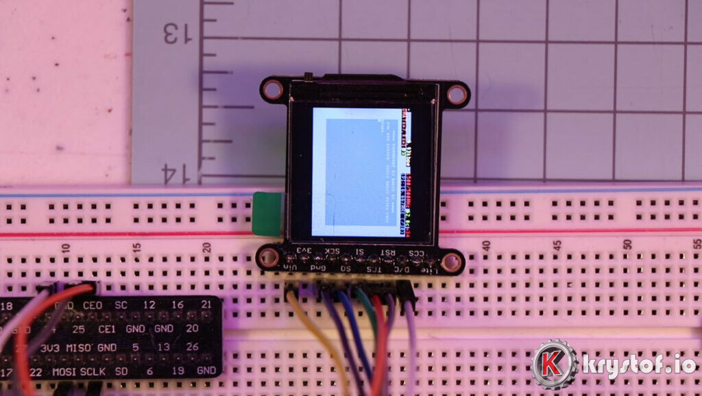

Okay, we can fix this. Reading up on a reported issue in the project’s GitHub issues list, I found reference to a couple of items to change in the code:
define DISPLAY_OUTPUT_LANDSCAPE - If we comment this out, we'll rotate the display 90 degrees - which way though? Let's try and find out what happens.
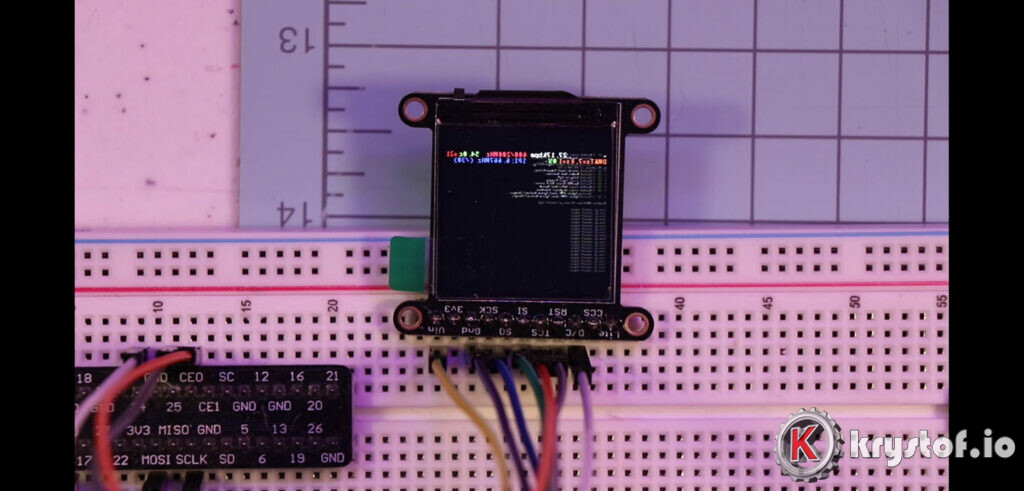

So we’re rotated properly, but we’re reversed. The text should be on the left. So we need to reverse the image, not just a simple rotation. Here’s the next changes I tried:
madctl ^= MADCTL_COLUMN_ADDRESS_ORDER_SWAP;  - Adding this line into another file will mirror image the display - Sold!

-DSTATISTICS=0 Remove that debug information
So, we try this change and rebuild, and we now have…
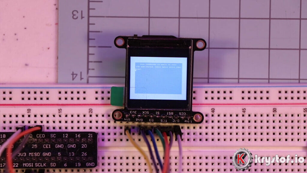

Now we’re getting there! We’re oriented in the right way, and the image reads left to right. Only thing now is to change the scaling, which is how my research led to this option:
-DDISPLAY_BREAK_ASPECT_RATIO_WHEN_SCALING=ON - I expected something like this because our display is 240 wide, so it's scaling 180 on the vertical to maintain aspect ratio. Let's just make it fill the whole thing so we don't have the black bars of doom.
And now….
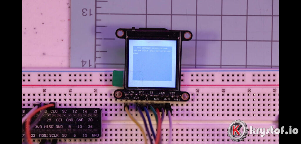

So now I’ve got both options working in the same fashion. There are differences though, and we’ll cover that in the next section below, after the ‘install instructions’
Install Instructions for Option 2 – fbcp-ili9341
Our goal is to download fbcp-ili9341, perform some quick modifications to the code, set our options, compile, and execute it.
If necessary, download the dependencies required:
sudo apt-get install cmake
Then let’s download our source code:
mkdir ~/fbcp-ili9341
cd ~/fbcp-ili9341
git clone https://github.com/juj/fbcp-ili9341.git
This creates and downloads the source to /home/pi/fbcp-ili9341/fbcp-ili9341 (Yeah, it’s a double directory, I always make my own root directories for compilation work)
Before we compile, we need to make the edits referenced in our previous section on figuring out how Option 2 was going to work.
Edit your config.h file:
nano ~/fbcp-ili9341/fbcp-ili9341/config.h
Comment out the line below (the example is already commented out)
//#define DISPLAY_OUTPUT_LANDSCAPE
Next, we’ll edit our ST7789 (actually it’s a file that handles a couple of ST-made chips) specific file to do the ‘mirroring’ swap. Edit the following:
nano ~/fbcp-ili9341/fbcp-ili9341/st7735r.cpp
and add the following line:
madctl ^= MADCTL_COLUMN_ADDRESS_ORDER_SWAP;
somewhere before this line:
SPI_TRANSFER(0x36/MADCTL: Memory Access Control/, madctl);
Optional Gamma Change: I’ve also, over time, discovered that I like the screen a little darker, primarily because I have a camera pointed at it at the Twitch stream and it causes some overexposure of the screen compared to the diorama itself. So you can make the gamma 1.0 by changing this line in the same file:
SPI_TRANSFER(0x26/Gamma Curve Select/, 0x04/Gamma curve 3 (2.5x if GS=1, 2.2x otherwise)/);
Change the 0x04 to 0x08:
SPI_TRANSFER(0x26/Gamma Curve Select/, 0x08/Gamma curve 3 (2.5x if GS=1, 2.2x otherwise)/);
That’s it for file editing, let’s get back to the compile.
cd ~/fbcp-ili9341/fbcp-ili9341
mkdir build
cd build
cmake -DST7789=ON -DGPIO_TFT_DATA_CONTROL=24 -DGPIO_TFT_RESET_PIN=25 -DSPI_BUS_CLOCK_DIVISOR=30 -DSTATISTICS=0 -DDISPLAY_BREAK_ASPECT_RATIO_WHEN_SCALING=ON ..
make -j
This will create the fbcp-ili9341 binary in the build directory. Try it out by running it and hitting CTRL-C when you’re done.
sudo ./fbcp-ili9341
If that works nicely for you, you could also make a quick hack to your /etc/rc.local file and make it boot on startup. (This is a quick hack)
#Copy fbcp-ili9341 and start it up on boot
sudo cp ./fbcp-ili9341 /usr/bin
sudo chmod +x /usr/bin/fbcp-ili9341

sudo nano /etc/rc.local
Add the following line to rc.local before ‘exit 0’.
sudo /usr/bin/fbcp-ili9341 &Comparing Mirroring Options
You may notice right off the bat that the default initialization of our option 1 vs option 2 have a stark difference in brightness. I didn’t investigate further in making the first option brighter, because I was just so happy with option 2 as a whole I never looked back.
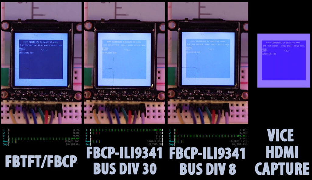

Option 2, as you can see in the video segment at the beginning of this article, has a much higher frame rate as promised. While I did try two different arguments to the SPI_BUS_CLOCK_DIVISOR option (30 and 8), I really didn’t see much of a difference in my eyes. The big difference is between fbtft/fbcp being much slower than fbcp-ili9341.
What’s the trade-off? As you see in the video, there’s about a 20-40% spike in one of my Pi’s cores on FBCP-ILI9341 vs regular old FBCP. Given I’m using a beefy Raspberry Pi, I detected no issues in game play. Your mileage may vary.
So we’ve now got part of our diorama circuitry working – we successfully mirrored the Raspberry Pi HDMI output to the ST7789 driven LCD display, showing whatever we play on our VICE Commodore emulator’s HDMI output. There’s more to come, though! Remember those 1541 disk drives that Commodore computers utilized? Well, we need to make sure that the LEDs we plan on putting in those floppy drives light up according to activity in VICE. To do that, we’ll need to create a custom VICE build (we’ll be doing a small bit of C programming) so we can drive LED activity and power LEDs based on whatever VICE is doing. That will be the next article in the series, coming soon.
References and Further Reading
SPI – Serial Peripheral Interface
https://learn.sparkfun.com/tutorials/serial-peripheral-interface-spi/all
https://en.wikipedia.org/wiki/Serial_Peripheral_Interface
https://www.raspberrypi.org/documentation/hardware/raspberrypi/spi/README.md
https://learn.adafruit.com/circuitpython-on-raspberrypi-linux/spi-sensors-devices
Option 1 – FBTFT/FBCP
https://github.com/notro/fbtft
https://github.com/notro/fbtft/wiki/Development
https://github.com/torvalds/linux/blob/master/drivers/staging/fbtft/fb_st7789v.c
https://github.com/notro/fbtft/issues/425
https://www.rhydolabz.com/documents/33/ST7789.pdf
https://github.com/tasanakorn/rpi-fbcp
Option 2 – FBCP-ILI9341
https://github.com/juj/fbcp-ili9341
Raspberry Pi GPIO Information
https://www.raspberrypi.org/documentation/usage/gpio/
Adafruit
.96″ OLED Product Page (Not the display I ended up going with for resolution reasons, otherwise it’s very nice.)
1.3″ 240×240 TFT LCD Product Page (My ultimate choice for this diorama)
Tutorial/Learning Page for the 1.3″ display (wiring, python, etc.)
VICE
The Elder Scrollers Demo by Booze Design
Sooo many thanks for the 0x37 hint. I rotated the image (0x36, 0xC0) and got stuck at the CASET and RASET commands in the data sheet. Until I Duckduckgoed myself here. Thanks!!
Ferenc, you’re quite welcome! I’m really glad this helped somebody else, because that’s exactly why I wanted to post this article – I was hoping someday I’d hear about this extremely chipset specific note working for someone. Cheers!
In the guide (“wire before you fire”) you say you use gpio24 for RESET and gpio25 for DC, but in the command line options it is vice versa, or do I miss something?
Thomas, that’s a good find. I’m embarrassed to have such a glaring error there. I will rectify that, but yes, whichever pin you choose for the reset pin on the LCD should be the reset pin in your configuration, and same for the data control pin.
Okay, this helped a LOT. The only question I have is will this work with the Adafruit PiTFT addon, or will I need a different setup?
Glad it helped, Jag. I recently used a PiTFT wired up to my raspberry PI for a different diorama (my MS DOS Gaming diorama that I’m still designing) – and you won’t have to worry about the ST7789 specifics, as it’s a ILI9341 chipset. But it definitely worked, and there’s plenty of variants and troubleshooting issues on https://github.com/juj/fbcp-ili9341, if you go that route (which I recommend over plain old fbcp). So I’m not sure what ‘setup’ you mean, but juj’s driver will work with the PiTFT.
I’m moving next week so I won’t be available to test or share any wiring pinouts I used with it until early April, but might be able to guide you to some other pieces to look at if you have any issues.
Hi there…I’ve followed your instructions to the letter and it “looks” like its working on the software side, but I can’t seem to get the hardware working. I have turned on in the software setup the pin output and the IPS, but all I get on the screen is the backlight. Is there anything else I need to do software wise to get this working? It looks like to me the PIZero I have is not sending info to the GPIO? Help!
David,
It just so happens I have a PiZero around here I can test this out with. I’ve not tried that display and a PiZero before but I’ll verify it works with a Pi 4 first just to make sure. Are you looking to utilize fbcp-ili9341 and a ST7789 display, or do you have different hardware?
David,
I was able to reproduce the issue you were seeing on a PI Zero. Next step is to take a fresh Pi 4 and do the same thing. Certainly possible some recent software update or the Raspbian distro changes caused an issue. I’ll reply here with results when I have some.
David, I found out something useful and just tried it out – with success (somewhat)
Check this out:
https://github.com/juj/fbcp-ili9341/issues/125
It essentially says to augment your cmake command with the additional parameter -DUSE_DMA_TRANSFERS=OFF. This is most likely not ideal, but it’s some movement at least.
Keep an eye on that issue as it seems to be specific towards the Pi Zero and (possibly) the ST7789 chipset.
I encounter the same issue: only backlight on, running fbcp-ili9341 on RaspPI-4B.
Meanwhile, I have to say that my display is a 240×240 on which the pins are like this:
GND, VCC, SCK, SDA, RES (¿reset?), DC (¿dataControl?), BLK (backlight).
My pinout goes like this:
SI7789- wire color – RaspPi PIN
GND – NOIR – 20.GND
VCC – BLANC – 17.VCC
SCK – VIOLET – 23.SCLK
SDA – BLEU – 19.MOSI
RES – VERT – 22.GPIO 25
DC – JAUNE – 18.GPIO 24
BLK – ORANGE – 24.CEO
Am I doing something wrong on pinout ?
Hello all,
big big thanks to you, Eric for all that.
According to https://github.com/juj/fbcp-ili9341/issues/125 (link given by Eric bellow), I desactivated all references to «
ALL_TASKS_SHOULD_DMA ».On top of that, I compilated the prog with the -DUSE_DMA_TRANSFERT=OFF option (as suggested on compilation screen).Still: same result; only backlight is on.Meanwhile, on HDMI screen, the display seams to be recognized as it says:"Source GPU display is 768x1360. Output SPI display is 240x240 with a drawable area of 240x240. Applying scaling factor ....scaleWidth: 240, scaleHeight: 240"So ... I'm back questionning the pinout.The Picomori Pico Display goes like the following list:
Picomori RaspPico
33.AGND — 33. AGND
32.ADC1 — 32.GPIO27_ADC1
31.ADC0 — 31.GPIO26_ADC2
30.RESET — 30. RUN
26.BL_EN — 26.GPIO20
25.MOSI — 25.GPIO19
24.SCK — 24.GPIO18
23.GND — 23.GND
22.CS — 22.GPIO17
21.DC — 21.GPIO16
I’ll try (down) and let you know
Picomori — RaspPico
30.RESET — 30. RUN
26.BL_EN —26.GPIO20
25.MOSI —25.GPIO19
24.SCK —24.GPIO18
23.GND —23.GND
22.CS —22.GPIO17
21.DC —21.GPIO16
The previous message (refering to PICO) gave me nothing better on Rasp PI 4b.
I tried to swap orange et green wires: useless. Still the backlight on with no image on screen.
Patrick,
I do hope somebody on here has run across this and can give some guidance. I unfortunately can’t do much at the moment as I’m swamped with a large work project – but I do hope you’re able to get it resolved, and if you do, please drop a line and let me know! Good luck!
Hey Eric,
I have a Pirate Audio board with a 1.3″ IPS colour LCD (240x240px) (ST7789 driver) but i can’t get it to work. All the “pimoroni/st7735-python” examples do work. But still black screen.
Greets
Hi Thiago,
You’re trying to get it running with fbcp-ili9341 or the slower ‘fbtft/fbcp’ option? You’re saying the pimoroni/st7735-python examples work on your screen but the frame buffer copy does not, correct? Is this the item? https://www.mouser.com/new/pimoroni/pimoroni-pim476-lcd-breakout-board/
I’m not sure if you looked at the Adafruit resource on their ST7789 page (that’s the LCD I have) that has a general setup of that on the Raspberry Pi using Python to display their little snake logo. I did that as a test before I did anything with fbcp/fbtft or fbcp-ili9341. It could help from a diagnostic standpoint.
https://learn.adafruit.com/adafruit-1-3-and-1-54-240-x-240-wide-angle-tft-lcd-displays?view=all
(About halfway down, search for ‘ST7789 and ST7735-based Displays’ on the page)
Another quick search that looked like there might be some interesting discussion / coding examples is here:
http://moodeaudio.org/forum/showthread.php?tid=2065&pid=15784
Hope that helps in some way. Hard to diagnose much without the thing in front of me.
P.S. This thread might help too, it deals with Pirate Audio and actually linked back to this page for the 0x37 instruction.
https://forums.slimdevices.com/showthread.php?111502-Jivelite-on-a-Pirate-Audio-240×240-screen/page32
[…] The following page was extremelly helpful – See Option 2: Mirroring Raspberry Pi HDMI Video to a ST7789 1.3 inch LCD Display […]
will it work on pi 4 running linux os
Hi Vinod, I’ve only tested this on Raspbian on a Pi4, other variants I’ve not tried.
thanks for the reply
How did you connect the display with a HDMi video adapter
The LCD is wired to the Raspberry Pi’s GPIO pins, while the HDMI port of the Pi still works when connecting to a monitor. The outputs are mirrored, what you see on the LCD matches what you see on the HDMI output.